- 您现在的位置:买卖IC网 > Sheet目录346 > NCP5021MUTXG (ON Semiconductor)IC WHITE LED DVR HV AMB 16-UQFN
NCP5021
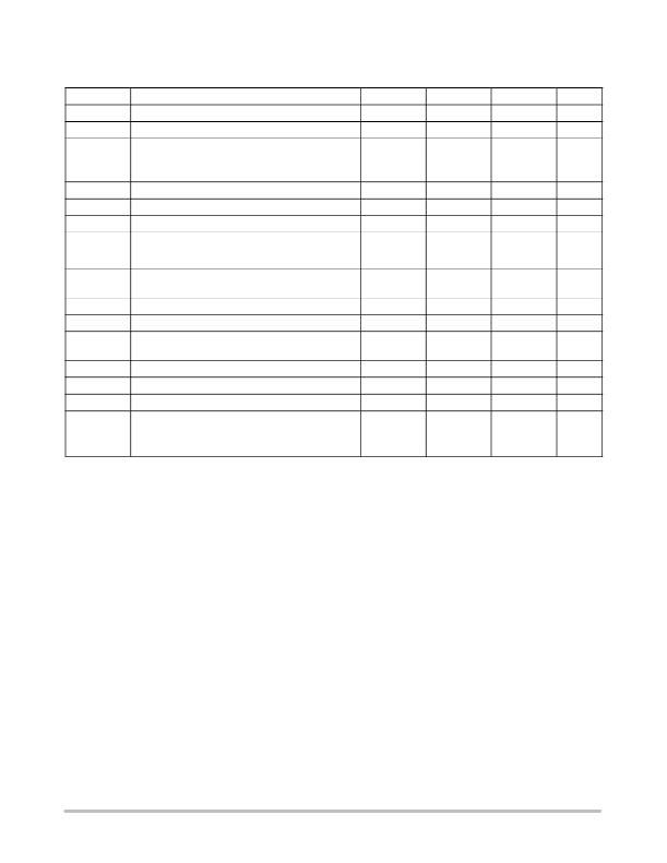
Table 3. POWER SUPPLY SECTION (Typical values are referenced to T A = +25 ° C, Min & Max values are referenced ? 40 ° C to +85 ° C
ambient temperature, unless otherwise noted), operating conditions 2.85 V < V bat < 5.5 V, unless otherwise noted.
Symbol
V bat
V UVLO
Rating
Power Supply Operating Range
Power Supply Undervoltage Lockout
Min
2.7
2.0
Typ
2.2
Max
5.5
2.4
Unit
V
V
V UVLOHY
I out
I LKLX
Undervoltage Lockout Hysteresis
Continuous DC Current in the load, V out pin
@ 3.0 V< V bat < 5.5 V
Power Switch Leakage Current (Lx pin) @ I out = 0
25
150
200
mV
mA
nA
V OVP
Output Voltage Overvoltage Protection
30
32
34
V
V OVPHYS
t start
I STBY
OVP Output Voltage Hysteresis
DC/DC Start time (C out = 4.7 m F),
3.0 V < V bat = nominal < 5.5 V
from last ACK bit to full load operation
Standby Current, V bat = 3.6 V, I out = 0 mA
1.5
600
1.0
V
m s
m A
@ SCL = SDA = H (no port activity)
I op
Operating Current, @ I out = 0 mA, V bat = 3.6 V
2.0
mA
I PK
I TOL
F PWR
T SD
T SDH
E PWR
Maximum Inductor Peak Current
Output Current Tolerance @ V bat = 3.6 V, I LED = 10 mA,
? 25 ° C < T A < 85 ° C
Boost Operating Frequency, ? 40 ° C < T A < 85 ° C
Thermal Shut Down Protection
Thermal Shut Down Protection Hysteresis
Efficiency @ V bat = 3.6 V, ESR < 150 m W ,
Coilcraft = LPO3310 ? 472ML, C out = 1.0 m F (Note 5)
I LED = 10 mA, Vf = 2.85 V
I LED = 25 mA, Vf = 3.4 V
? 10%
1.13
855
± 1
1.30
160
30
75
80
+10%
1.47
mA
%
MHz
° C
° C
%
5. Using low ESR inductor with low Eddy current losses is mandatory to get the high efficiency operation.
http://onsemi.com
4
发布紧急采购,3分钟左右您将得到回复。
相关PDF资料
NCP5050MTTXG
IC LED DRIVR PHOTO FLASH 10-WDFN
NCP5111DR2G
IC DRIVER HI/LOW SIDE HV 8-SOIC
NCP5304DR2G
IC DRIVER HI/LOW SIDE HV 8-SOIC
NCP5355DG
IC DRVR SYNC BUCK MOSF 12A 8SOIC
NCP5359ADR2G
IC MOSFET GATE DVR DUAL 8-SOIC
NCP5359DR2G
IC GATE DRIVER VR11.1/AMD 8-SOIC
NCP5360RMNR2G
IC DRIVER MOSFET 56QFN
NCP5366MNR2G
IC DRIVER MOSFET DFN
相关代理商/技术参数
NCP502ASQ15T1
制造商:ONSEMI 制造商全称:ON Semiconductor 功能描述:80 mA CMOS Low Iq Voltage Regulator in an SC70−5
NCP502ASQ15T1G
制造商:ONSEMI 制造商全称:ON Semiconductor 功能描述:80 mA CMOS Low Iq, Low−Dropout Voltage Regulator
NCP502ASQ18T1
制造商:ONSEMI 制造商全称:ON Semiconductor 功能描述:80 mA CMOS Low Iq Voltage Regulator in an SC70−5
NCP502ASQ18T1G
制造商:ONSEMI 制造商全称:ON Semiconductor 功能描述:80 mA CMOS Low Iq, Low−Dropout Voltage Regulator
NCP502ASQ25T1
制造商:ONSEMI 制造商全称:ON Semiconductor 功能描述:80 mA CMOS Low Iq Voltage Regulator in an SC70−5
NCP502ASQ25T1G
制造商:ONSEMI 制造商全称:ON Semiconductor 功能描述:80 mA CMOS Low Iq, Low−Dropout Voltage Regulator
NCP502ASQ27T1
制造商:ONSEMI 制造商全称:ON Semiconductor 功能描述:80 mA CMOS Low Iq Voltage Regulator in an SC70−5
NCP502ASQ27T1G
制造商:ONSEMI 制造商全称:ON Semiconductor 功能描述:80 mA CMOS Low Iq, Low−Dropout Voltage Regulator